PlayStation 1 reset mod, part 2
Recap
A few months ago I bought a PSIO from Cybdyn System.
This device let’s you play games from an SD card on a PlayStation 1, a bit like krikzz EverDrives for older cartridge based consoles.
After playing around with it for a bit I saw a user on the PSIO forums ask for a way to reset the PlayStation 1 through a button combination.
Unfortunately the PSIO has no access to the status of the buttons on a controller, so this can’t be done from the PSIO.
I had messed around with the PlayStation 1 communication before and I was confident I could build something that would do just that.
From my previous post you can see I managed to make something that worked, but was not perfect.
In this article I’m going to explain what I did afterwards.
Video
But first here’s a video of the latest version working:
Disclaimer
This mod is a piece of hardware you add to the PlayStation. Although you don’t have to modify the motherboard, it still requires a bit of soldering.
I am not responsible if the PlayStation doesn’t work after you’ve installed or removed my mod.
If you don’t know what you’re doing, go to someone that does.
You do this at your own risk.
Caution
It goes without saying that resetting the PlayStation whilst you’re saving data can corrupt the save data and/or the memory card.
Do NOT reset the PlayStation when it is writing data to the memory card.
You have been warned.
Proof of Concept
Now that we’re done with all the legal bullshit, let’s talk about the previous versions.
The first mod used an Arduino Nano (ATMEGA328P) at 16MHz, powered with the PlayStation 3.5VDC. The program written for it uses the polling method to read the command and data between the PS1 and controller.
Although this works there are two issues:
- The Arduino Nano is underpowered for the 16MHz at which it’s running, so unexpected behaviour can happen. The datasheet specifies that anything above 8MHz needs to be powered from 5VDC.
- The polling method is unreliable as it does miss data, which means that the reset is not instantenious and takes a second. I also don’t like continiously polling for data.
Here is a flowchart I made of the first proof of concept code:

This version is also the one I’m talking about in the first article.
In the second proof of concept I tried to use interrupts to remove the polling loop.
I used the two INT interrupts and a timer. The first INT interrupt was looking at the SS signal.
Whenever the SS was pulled low, the interrupt would trigger and start the timer.
The timer would run for a few ms and when it overflowed it would check the SS signal again. If that was still low then it would enable the 2nd INT interrupt on the CLK.
The 2nd INT interrupt would trigger every rising edge and copy the state of the whole input port.
This data would then be rebuilt into the PlayStation CMD and DATA.
Unfortunatelly there where some issues with this that I still am not sure what the causes are.
One issue I found was due to the Playstation controller being powered from 3.5VDC and the Arduino Nano from 5V. The voltage of the signals from the PlayStation were sometimes in the unknown region of the input pin of the Arduino due to resistance, load, etc.
The concept was nicer than the polling loop but it didn’t work. Maybe with a bit more time and troubleshooting this could have worked, but I found that the effort I put into this was waisted due to there being a better way to do this.
Here’s the flowchart for the 2nd proof of concept:

The communication from the PlayStation with the controller is basically SPI, which means that I needed a microcontroller with two SPI modules to be able to read the command and data signals. Because of this I choose the ATMEGA328PB which is an improved version of the ATMEGA328P that has two SPI modules.
And so the 328PB was going to be used in my 3rd proof of concept.
I removed the ATMEGA328P from an Arduino Nano and soldered on an ATMEGA328PB, because they’re pin compatible. The neat thing about this is I have a board that works with the 328PB without any issues, and it has a CH340 USB to UART converter.
The code was written in Atmel Studio and I flashed the ATMEGA328PB with an old USBasp a friend of mine made years ago.
I programmed it so that it would use both SPI modules to read the command and data, without having to make workarounds like in the previous concepts.
This proof of concept worked perfectly, but there were some things that could be improved:
- The microcontroller was big, too big for what it needed to be. Big in the essence of too many I/O, too much memory, etc.
- The ATMEGA328PB, like the 328P version, can’t run at more than 8MHz if it’s powered at 3.3VDC and I felt that that wouldn’t have been enough (even though it probably wold have been fine).
First release
After the 3rd proof of concept I looked at what microchip had available and the 16F18325 was the cheapest microcontroller with two SPI modules.
The 16F18325 can be powered by the 3.5VDC and use it’s internal oscillator with PLL to go up to 32MHz.
So that’s what I’m using in the new mod.
I used MPLABX with the XC8 compiler and a PICKit3 to flash the microcontroller.
The awesome thing about the 16F18325 is that you can select which I/O is connected to which module.
If you look at the Arduino Nano and the ATMEGA28P, you’ll see that each I/O is connected to a module like the UART or the SPI or ADC, but those are fixed…
The 16F18325 can be customized to whatever configuration you want. If you want your UART TX & RX on RA1 & RA2, you can do that.
If it so happens that that wasn’t a good choice, due to for example board layout, you can change the UART TX & RX to somewhere else.
This is amazing! The customizability of the 16F18325 and other microcontrollers like this one is endless.
Each SPI module has a CLK, SS, MISO and MOSI. Because we don’t reply to the data sent, we don’t need MISO.
So those would usually take 6 I/O pins, but thanks to the 16F18325 we can do this with 4 I/O.
The CLK and SS are the same for both SPI modules, so the program connects both SPI CLK to the same I/O. Same thing for the SS.
The MOSI inputs are internally connected to different pins which in turn are connected to CMD and DATA.
And this works perfeclty fine like you can see in the video above.
I have also setup the SPI inputs to be different than the ICSP connections. Although I wouldn’t recommend you to flash the microcontroller when it’s connected to the PlayStation 1, you could.
/*
 Connection:
    RA2 = SS
    RC0 = CLK
    RC1 = DATA
    RC2 = CMD
    SDO1,2 = unassigned
    RC5 = RESET
 */

 // ...

    // SETUP SPI1 & SPI2 I/O
    SSP1SSPPSbits.SSP1SSPPS = 0x02; // SS1 = RA2
    SSP2SSPPSbits.SSP2SSPPS = 0x02; // SS2 = RA2

    SSP1CLKPPSbits.SSP1CLKPPS = 0x10; // SCK1 = RC0
    SSP2CLKPPSbits.SSP2CLKPPS = 0x10; // SCK2 = RC0

    SSP1DATPPSbits.SSP1DATPPS = 0x11; // SDI1 = RC1
    SSP2DATPPSbits.SSP2DATPPS = 0x12; // SDI2 = RC2
The first release on the github repository contains everything you need to make the board and flash the 16F18325.
Schematic and PCB
Below you’ll find the schematic and a 3D render of the PCB.
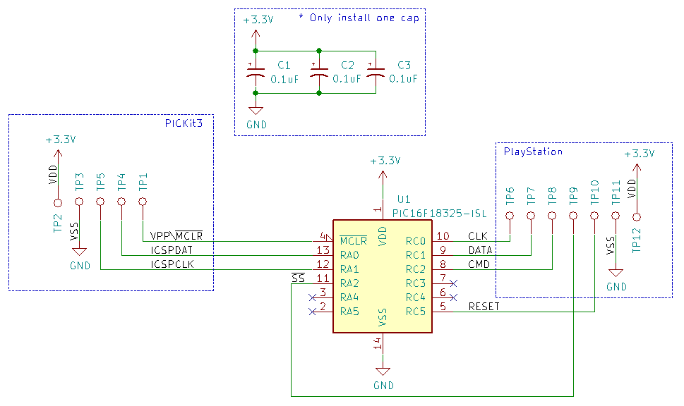
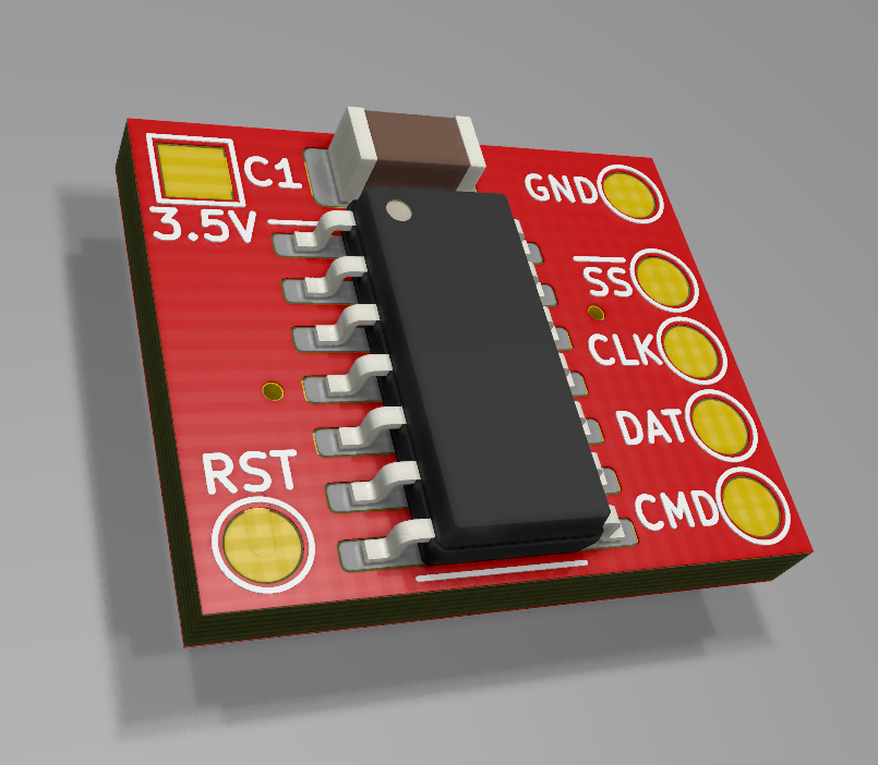
The PCB is 14.5mm by 12mm, so it’s small. The solder pads should be 1.5mm wide.
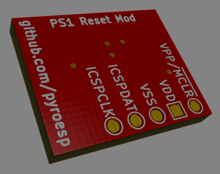
The pads on the back are smaller because they’re only used for flashing the fimware.
After flashing, put some tape on the back so these don’t make contact with anything on the motherboard.
A guide is being made so that everyone can install this mod in their PlayStation 1.
Making the PCB
By downloading the first release on the github repository you’ll get the firmware and the gerber files for the PCB.
Go to JLCPCB and click on the “Quote Now” button for the PCB prototype. These are 2$ for 5 boards (not including shipping).
Upload the gerber files to JLCPCB like they ask you to.
If you don’t know what to select in the parameters below, then these are my settings:
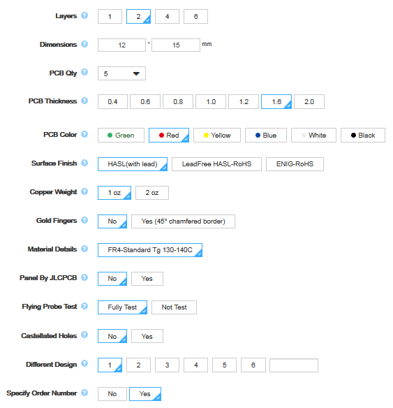
At the time of writing you can change the PCB width from 1.6 to 0.6mm without additional cost.
Green is the default color, but changing it doesn’t add cost. It does add a day or two in the fabrication of the PCB.
Changing buttons
Changing the button combination is trivial to do.
Checkout the last chapter in the first part of this mod blog post. I have explained how to do it there.
Once done, recompile and flash the microcontroller.