PlayStation 1 reset mod
I’ve recently acquired a PSIO from Cybdyn System.
It’s a device that’s plugged into the parallel port of a PlayStation 1.
It allows you to play games from an SD card instead of a CD.
If you’ve ever had or heard about Krikzz EverDrive SD cartridges for older consoles, well it’s similar to those.
When you first start the PlayStation with the PSIO plugged in, a menu pops up where you can choose your game.
The only thing missing to the PSIO is a way to get back to this menu once a game has been launched.
Here’s where my mod comes into play.
The purpose of the mod is to be able to reset the PlayStation with a button combination on controller 1, so that you don’t have to get up to reset the PS1.
If you use the code as is then the reset button combination is L2+R2+START+SELECT for a digital/analog controller and A+B+TRIGGER for a GUNCON.
One thing to note here is that because the controllers are slave devices to the PlayStation, the PS1 won’t reset if it freezes as the communication just stops.
Video
Here’s a quick video showing off the mod in action with a digital controller.
Disclaimer
I’m not responsible for anything you do with this mod.
You do this at your own risk.
If something blows up… You probably fucked up somewhere.
Parts needed
This mod uses an Arduino Nano, 4x 1k Ohm resistors and 1x 500 Ohm resistor or 2x 1k Ohm in parallel.
You’ll also need some wire.
You can find the reset mod program for Arduino Nano here:
https://github.com/pyroesp/PlayStation-1-Reset-Mod.
Installing the mod
First of all, flash your Arduino Nano with the reset mod program mentioned above. If you don’t know how to do this, google it.
We will remove the USB to UART chip so you won’t be able to program the Arduino Nano once it’s installed.
The next steps are just describing how I did it on my PU-18 motherboard and where I placed the Arduino.
You don’t have to follow this. If you think you’ve found a better place to hide the Arduino then go for it.
Update 13/07/2019: The use of the Arduino Nano as described below is actually underpowering the microcontroller.
Looking at the ATMEGA328P datasheet, if you use a 20MHz crystal oscillator then you have to power the microcontroller with 4.5V to 5.5V.
Because it is underpowerd, it could not work as intended. Mine is working fine, but yours might not.
You can power it from the PlayStation 5V by connecting the 5V supply directly to the 5V pin of the Arduino Nano, not the VIN!
I would recommend you add a diode, from the PS1 to the Arduino Nano, as to block the USB 5V from powering the PlayStation motherboard.
Even though the PlayStation input/outputs are 3.5V, the Arduino Nano is always sinking current.
This means that the Arduino Nano never outputs a logic 1 (or 5V) to the PlayStation and thus it’s safe to connect it, even if it’s powered from 5V.
If you do this, then you won’t have to desolder the voltage regulator, nor the CH340 chip.
You’ll also be able to update the firmware on the Arduino Nano without blowing a fuse.
The Arduino Nano will use the controller 3.5V from the PlayStation so I removed the AMS1117 5V voltage regulator.
I also removed the CH340 chip, as I won’t have to use the serial port anymore, and some misc caps/diode.
This way only the ATMEGA328P will be powered by the PlayStation, plus it makes the bottom of the Arduino Nano flat.
Note: If you keep the Arduino Nano as is and plug it into your computer via USB after you installed it in the PS1, you are going to put 5V on the PlayStation 3.5V.
This will do 3 things:
- Send 5V to the controller through the 3.5V connection: might break stuff, I don’t know…
- Send 5V to the PlayStation through the 3.5V connection: might break stuff, I don’t know…
- Blow the controller 3.5V fuse (PS605): definitely broken, no more controller or memory card detected until the fuse gets replaced.
If you didn’t change the I/O from the code then these are the pins you need to solder resistors to.
- PB5 - SCK (input, connect to PS1 clock)
- PB4 - CMD (input, connect to PS1 TX)
- PB3 - DATA (input, connect to PS1 RX)
- PB2 - /SS (input, connect to controller 1 select)
- PB1 - playstation reset (output, connect to reset of parallel port (pin 2))
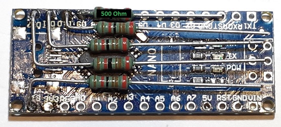
The PlayStation reset pin or PB1 has a 500 Ohm resistor. 1k was too much to pull the reset low.
You could use 2x 1k Ohm resistors in parallel here instead.
All other I/Os use the 1k resistors.
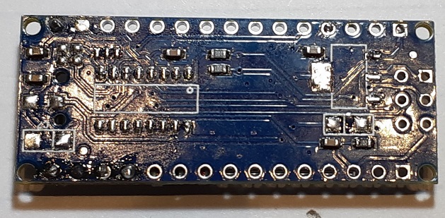
Next you’ll connect the Arduino Nano to the PlayStation.
This is where I connected them:
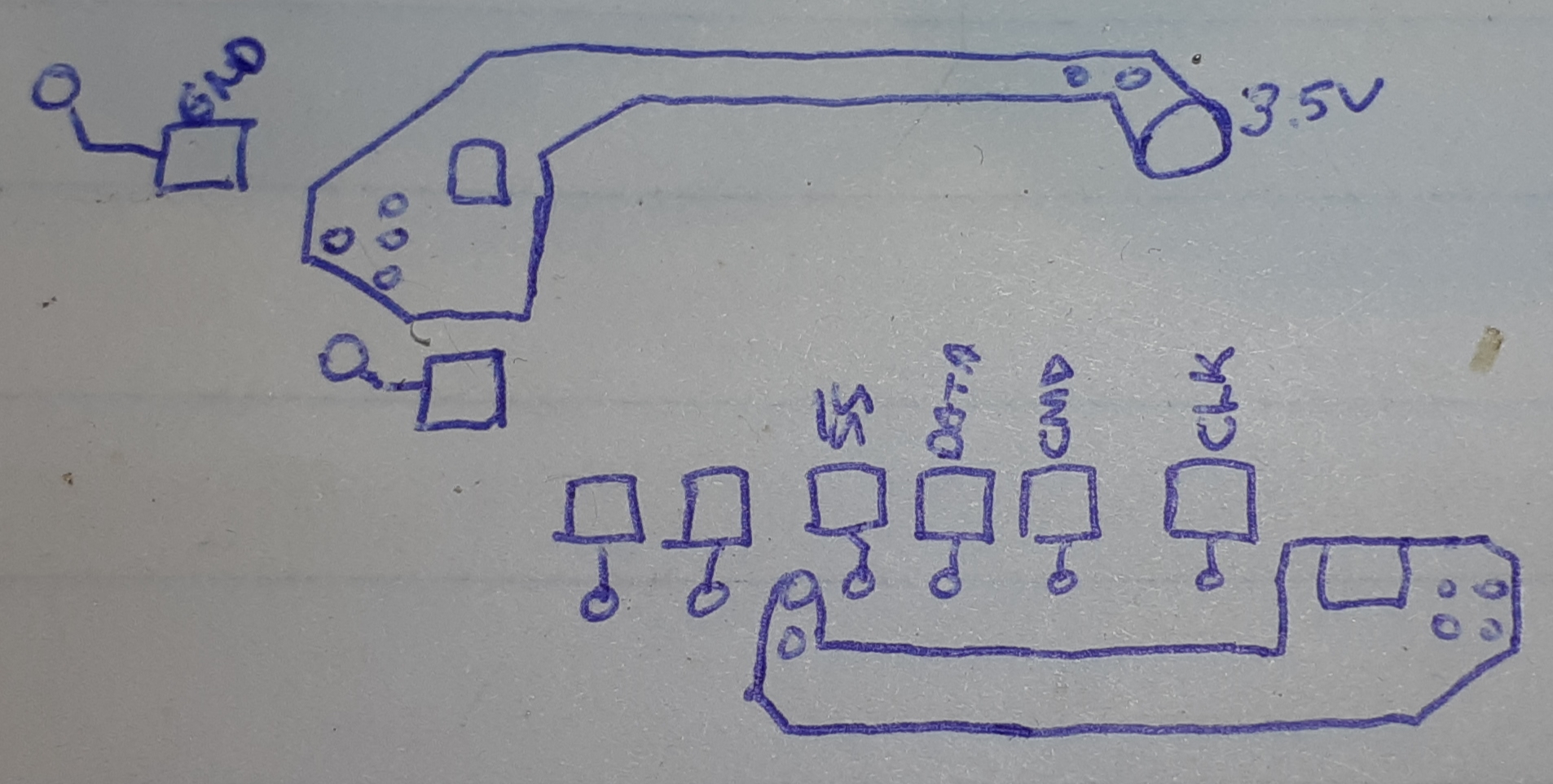
Here’s a drawing of the connections you’ll need.
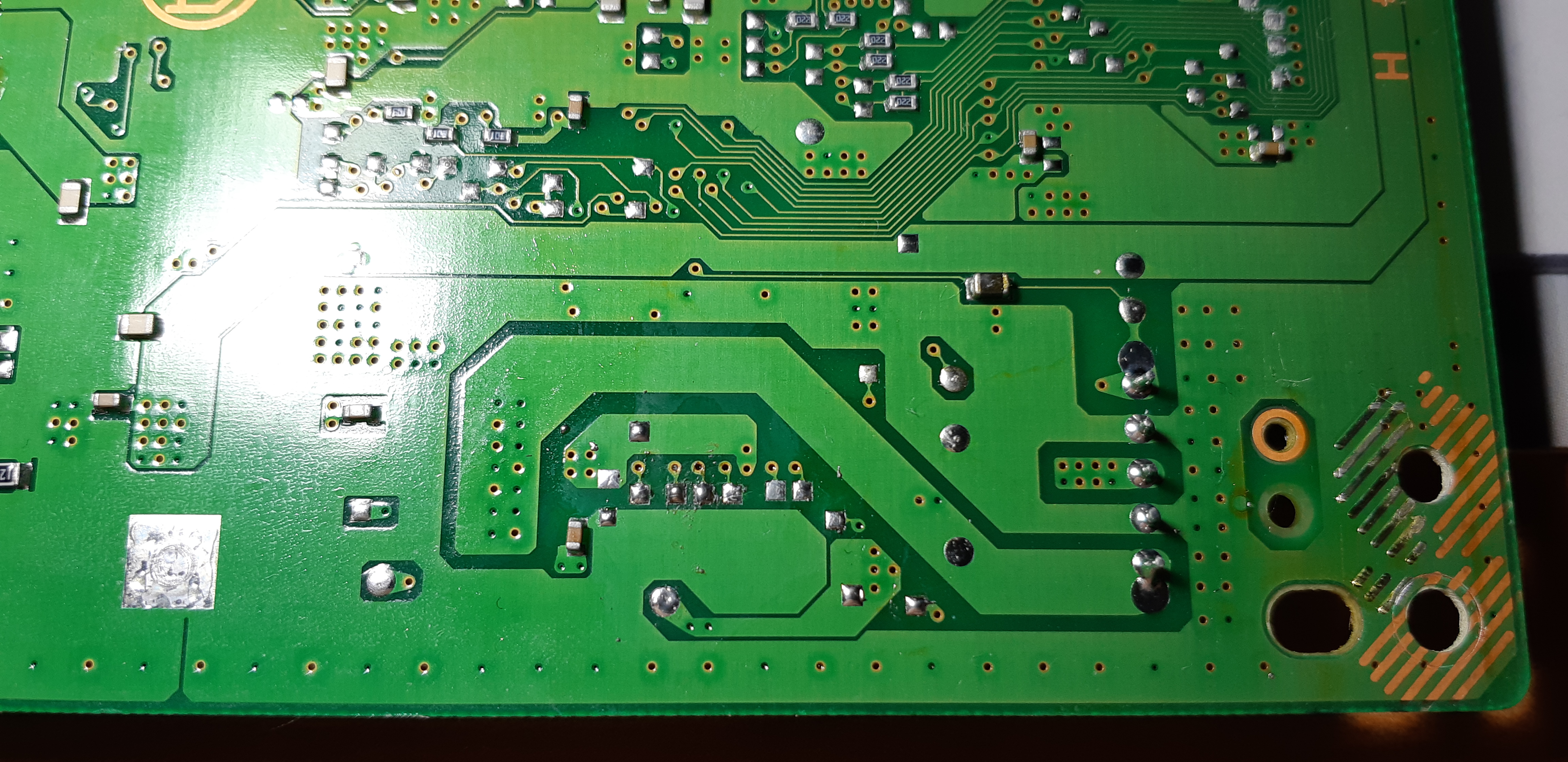
Here’s an extra image so you can see where this is located.

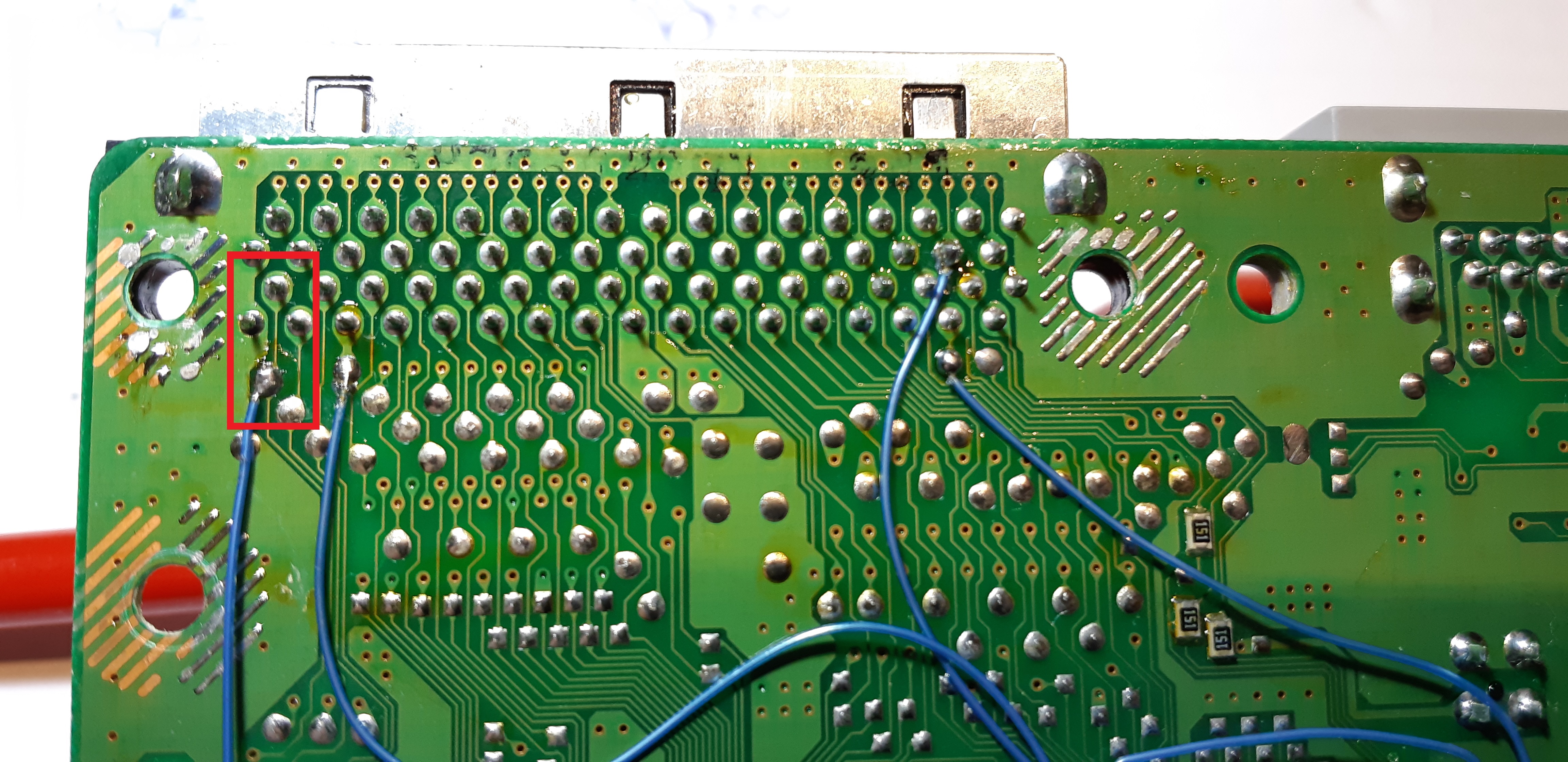
The PlayStation reset can be connected on pin 2 of the parallel port as shown below:
For power you want to connect the 3.5V of the PlayStation to the 5V of the Arduino Nano.
Don’t forget the GND either.
This is where I placed my Arduino Nano:
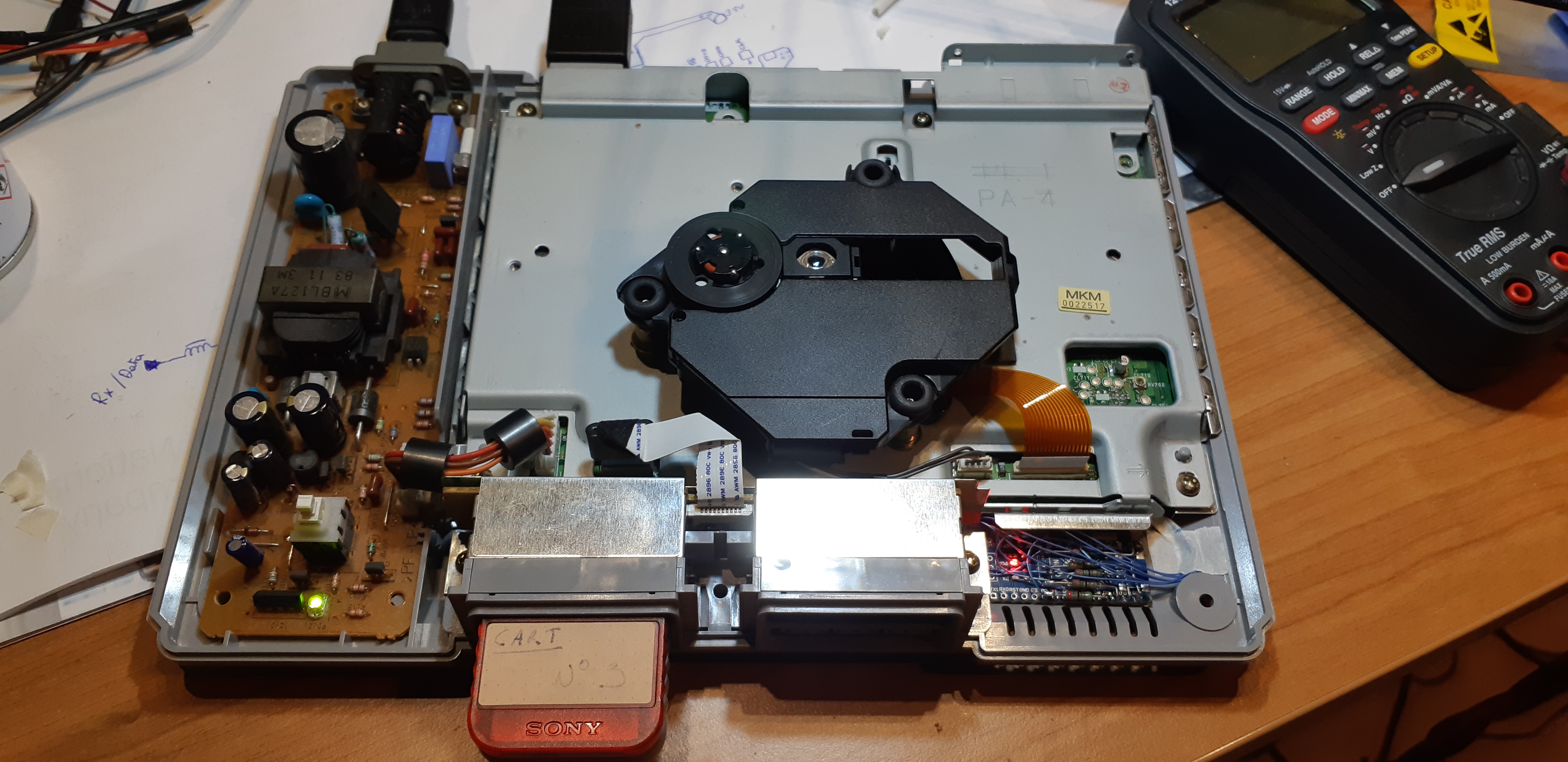
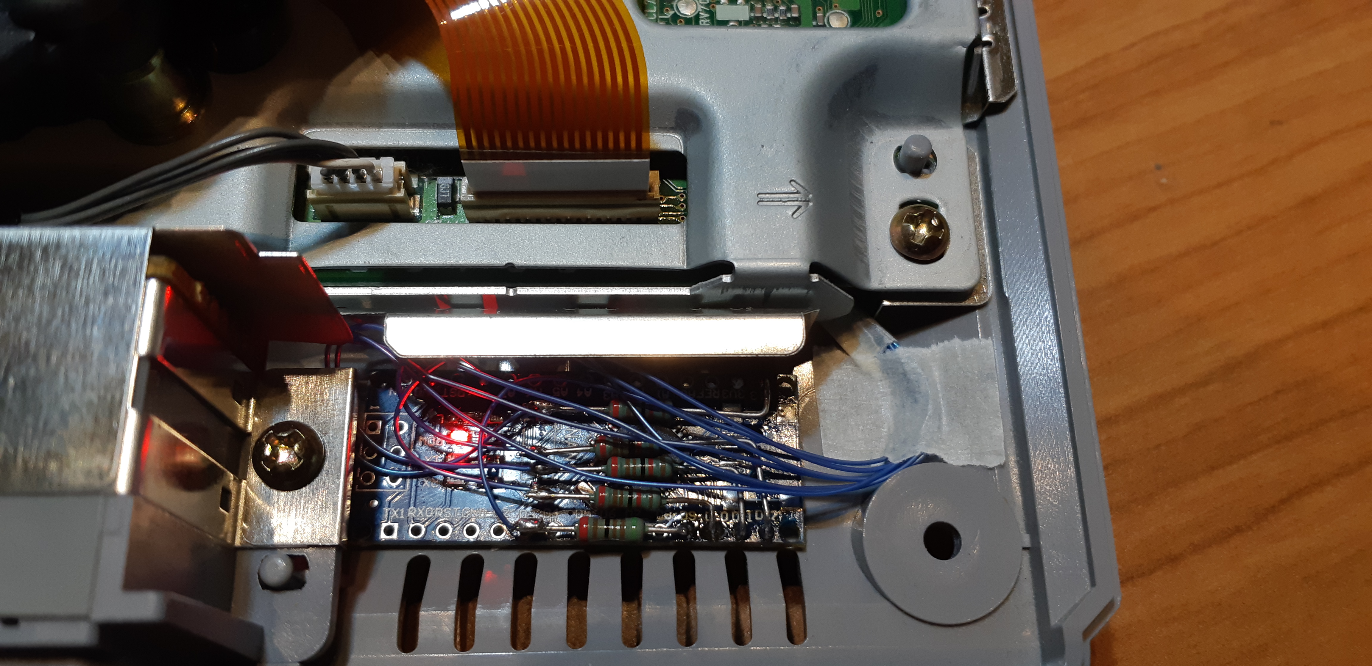
I used some tape on the bottom of the Arduino so it wouldn’t move.
All the wires are taped too. I also routed the wires with tape on the bottom side of the motherboard so they wouldn’t get pinched or crushed when assembling it all back in one piece.
Controller communication
I previously tried to decode PlayStation controller data so I already know what it looks like.
NOCASH from problemkaputt has a ton of information about the PlayStation and its controllers.
In short, the PlayStation uses a serial IO which resembles SPI.
From the PlayStation schematics you can see that there’s a TX, RX, CLK and CS. Both memory cards and control port share the same bus.
In addition to the bus and to, I assume, save on IO pins, controller port 1 and memory card 1 share the same CS. Controller port 2 and memory card 2 share a different CS.
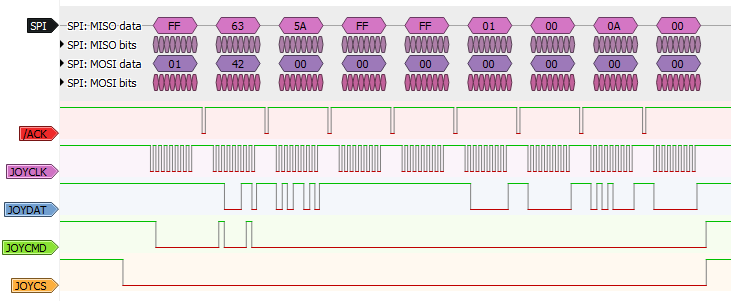
To differentiate a controller from a memory card the first byte transmitted from the PlayStation is the address of the device it will access.
A byte of value 0x81 will access the memory card. A byte of value 0x01 will access the controller.
Add to that the CS and it can read the 4 devices plugged in.
The PlayStation will then send a read command, which is byte value 0x42.
For a controller, the next 2 bytes sent are its ID.
For example, the value 0x5A41 is the ID of a digital controller.
After that comes the switch data.
Thanks to NOCASH, I know there are a maximum of 9 bytes that are sent after a controller read command.
Reading TX and RX
The Arduino Nano is connected to CS, CLK, TX and RX.
It will only read TX and RX when the CS of port 1 goes low and on the rising edge of CLK.
Reading TX and RX is done through polling because I had a few issues trying to do it using interrupts.
Reading the data is initialised by the CS pin going low.
Then each rising edge of the clock, both TX and RX are read into a buffer.
Because TX and RX are on the same I/O port, I can just do as follows:
  while (!(PS1_PIN_IO & _BV(SS))){ // loop while SS is low
    clk = PS1_PIN_IO & _BV(CLK); // read clock input
    if (!prev_clk && clk){ // check for rising edge
      port[bit_cnt] = PS1_PIN_IO; // read port
      ++bit_cnt;
      if (bit_cnt >= PORT_BUFF_SIZE) // if all bits read, exit loop
        break;
    }
    prev_clk = clk;
  }
The PS1_PIN_IO is a define for PINB.
Once the data transfer is done, the next step is to reconstruct the TX and RX bytes.
Decoding the data
Decoding the data is fairly simple. For 8 saved PINB values in the buffer, get the TX and RX bits out of it and make 2 separate bytes.
  // convert port buffer bits to byte
  uint8_t i, j;
  for (i = 0; i < PS1_CTRL_BUFF_SIZE; i++){
    cmd.buff[i] = convert_buff_to_byte(&port[i*8], _BV(CMD));
    data.buff[i] = convert_buff_to_byte(&port[i*8], _BV(DATA));
  }
This is the buffer to byte conversion function:
uint8_t convert_buff_to_byte(uint8_t *p, uint8_t b){
  uint8_t i, retval;
  for (i = 0, retval = 0; i < 8; i++){
    if (p[i] & b)
      retval |= _BV(i);
  }
  return retval;
}
To further help me in decoding the data, I’ve created 2 unions containing structures.
The first one is used to store the TX bytes.
Once the buffer in this union is filled with data, you can use the structure to help in checking the device and the command.
/* PlayStation Controller Command Union */
union PS1_Cmd{
  uint8_t buff[PS1_CTRL_BUFF_SIZE];
  struct{
    uint8_t device_select; // 0x01 or 0x81
    uint8_t command; // 0x42 for read switch
    uint8_t unused[PS1_CTRL_BUFF_SIZE-2]; // always 0 for controller
  };
};
Same for RX, once the buffer is full, you can access the ID, the switches and the analog joysticks/light gun coordinates from the structure.
/* PlayStation Controller Data Union */
union PS1_Ctrl_Data{
  uint8_t buff[PS1_CTRL_BUFF_SIZE]; // buffer to read data
  struct{
    uint8_t unused; // always 0xFF
    uint16_t id; // 0x5Ayz - y = type; z = # of half word
    uint16_t switches; // controller switches
    union{
      // light gun only (8MHz clock counter since hsync)
      uint16_t x_pos; // if 0x0001 then error, check y_pos
      struct{
        uint8_t adc0; // right joy X
        uint8_t adc1; // right joy Y
      };
    };
    union{
      //light gun only (scanlines since vsync
      uint16_t y_pos; // if x_pos = 0x0001 && y_pos = 0x000A => not aimed at screen
      struct{
        uint8_t adc2; // left joy X
        uint8_t adc3; // left joy Y
      };
    };
  };
};
Parsing the data
The data is checked against a few defines in the code.
First it’s going to check if the controller is the selected device and if the read command has been sent.
  // Check first command for device selected
  if (cmd.device_select == CMD_SEL_CTRL_1 && cmd.command == CMD_READ_SW){
Then it’s checking the ID of the controller.
    // Check ID
    switch(data.id){
      case ID_GUNCON_CTRL:
        // ...
        break;
      case ID_DIG_CTRL:
      case ID_ANP_CTRL:
      case ID_ANS_CTRL:
        // ...
        break;
I only have a digital controller, analog controller and GUNCON (light gun) so I have only programmed those IDs in the code.
#define ID_DIG_CTRL 0x5A41 // digital
#define ID_ANP_CTRL 0x5A73 // analog/pad
#define ID_ANS_CTRL 0x5A53 // analog/stick
#define ID_GUNCON_CTRL 0x5A63 // light gun
After that it’s going to check whether or not the reset button combination has been pressed against a predefined value.
/* Key Combo */
#define KEY_COMBO_CTRL 0xFCF6 // select-start-L2-R2 1111 1100 1111 0110
#define KEY_COMBO_GUNCON 0x9FF7 // A-trigger-B 1001 1111 1111 0111
Changing those defines will change the reset button combination.
Resetting the PlayStation
Once a reset command from the user has been detected, the Arduino Nano is going to pull the reset line of the PlayStation low for a few ms.
    // Check switch combo
    if (key_combo != 0 && 0 == (data.switches ^ key_combo)){
      // change RESET from input to output, logic low (PORT is already 0)
      PS1_DIR_IO |= _BV(RESET);
      delay(100); // hold reset for 100ms
      // change RESET back to input
      PS1_DIR_IO &= ~_BV(RESET);
      delay(REBOOT_DELAY); // wait 30 sec before next reset, this is to prevent multiple reset one after the other
    }
A reboot delay of 30 seconds is added so that the PlayStation can boot properly before getting a new reset command.
Changing button combination
If you want to change your combination, you’ll have to change the key combo defines shown above.
A pressed button returns 0 and all controllers send a 16 bit value for the switch status.
The switch is mapped as follows :
| Button | Bit |
|---|---|
| SELECT | 0 |
| L3 | 1 |
| R3 | 2 |
| START | 3 |
| UP | 4 |
| RIGHT | 5 |
| DOWN | 6 |
| LEFT | 7 |
| L2 | 8 |
| R2 | 9 |
| L1 | 10 |
| R1 | 11 |
| TRIANGLE | 12 |
| CIRCLE | 13 |
| CROSS | 14 |
| SQUARE | 15 |
The GUNCON buttons are:
- A = START
- Trigger = CIRCLE
- B = CROSS