Shooting bad guys
Some of you might remember the good old days of the PlayStation 1 and 2.
More specifically, I’m talking about Time Crisis and the GUNCON, aka G-CON45 for us Europeans.
For the sake of consistency, I’ll use GUNCON throughout the posts.
Now, in our modern time it’s rare to have a CRT TV. Everyone has flat screen and HD TVs.
I certainly don’t have a CRT TV anymore, which means I can’t enjoy Time Crisis and other GUNCON compatible shooting games.
We are in 2018 and there’s still no way to use the GUNCON on a flat screen TV.
This is going to change! Well… if everything goes according to plan, it should work.
Imagine a world, where GUNCONs use the same technology as the Wii remotes. Wouldn’t that be great ?
Before I go into the details of how to do this, let’s first talk about the GUNCON and the Wiimote.
GUNCON:
In 1994 (according to Wikipedia) the GUNCON, aka G-CON45, aka NPC-103, was released with the game Time Crisis.

The picture above (provided by Wikipedia) show the three GUNCON versions. Starting from left to right: GUNCON, GUNCON 2, GUNCON 3.
We will be taking a look at the first one.
The GUNCON, much like any other controller, gets plugged into the controller port of the PlayStation.
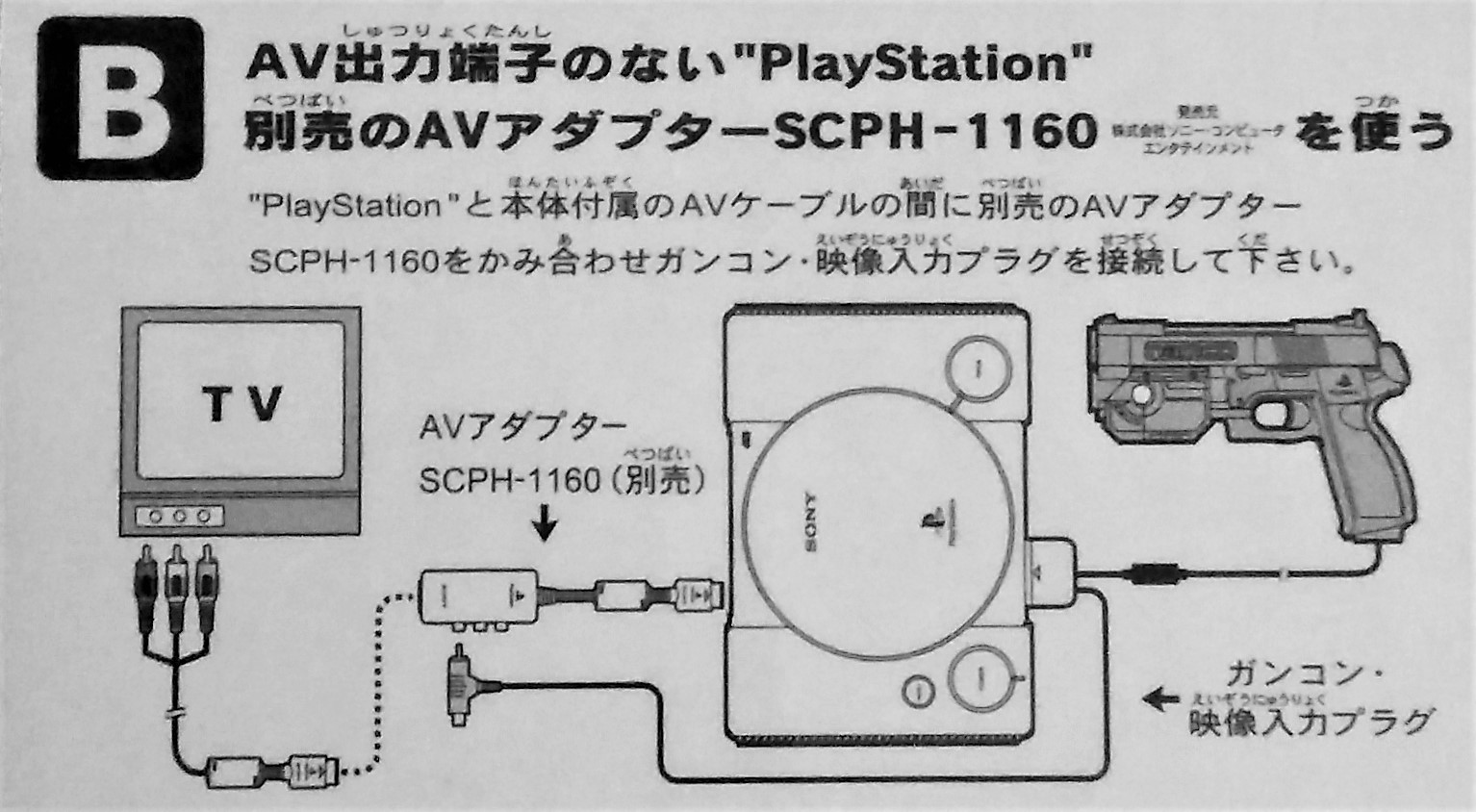
Additionally to that, you have to send the video signal to the GUNCON. This was done with an extra input at the GUNCON connector, see picture below:

The way the GUNCON works is through a technique called Cathode Ray Timing.
To my understanding, every V-SYNC resets the Y-coordinate, every H-SYNC increases the Y-coordinate by 1. The X position is determined by the press of the trigger, the timing between two H-SYNC and when the light sensor (photodiode) sees the change in brightness of the spot you’re shooting at on a CRT TV, due to the electron beam hitting the phosphor.
Then it’s just a matter of passing on those coordinates to the PlayStation and a bit of collision detection to determine if you hit a target or not.
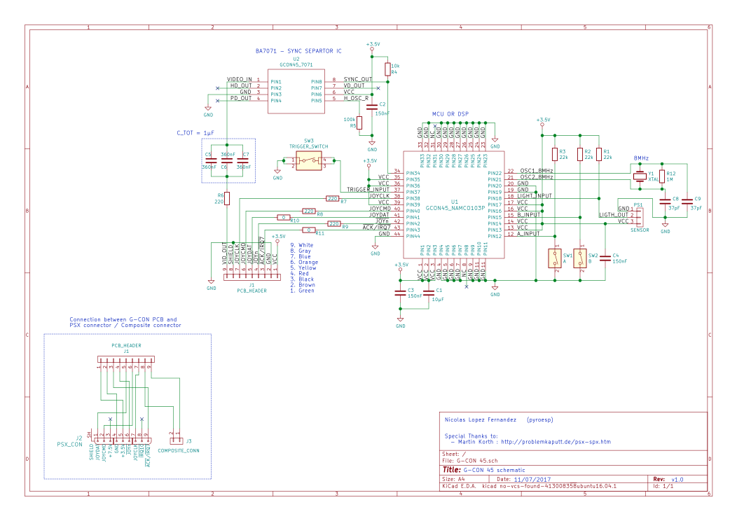
To further investigate the workings of the GUNCON, I reverse engineered the PCB inside of it.

For a better resolution, here’s the schematic in PDF.
The BA7071 chip (U2) is a sync seperator IC.
The sync pulses are sent to U1 which are then converted to X:Y coordinates whenever the trigger is pressed and sent to the PlayStation.
Let’s not worry about how the X:Y coordinates are sent to the PlayStation just yet.
If you’re curious about that, I’ll leave you this link which has a fuckton of information about the PlayStation and it’s controllers: https://problemkaputt.de/psx-spx.htm
Wii Remote:
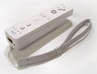
The Wii Remote, or Wiimote, is the controller of the Nintendo Wii. It’s a wireless (Bluetooth) motion sensing controller.

The Wiimote works in conjuction with the sensor bar, see image below:

The sensor bar has a few IR LEDs that shine at the player(s) in front of the TV.
The Wiimote has a camera behind an IR filter. This is a Motion Object Tracking module.
It can track points on a 2D plane and send the X:Y coordinate of those points.
The Wiimote also has an accelerometer and using both these sensors it can do motion sensing/tracking.
How the Wiimote uses the information to do this, I don’t know. What interests me is the MOT camera, able to track multiple points.
From other peoples research, it is known that the MOT module is a PAC7010 from PixArt, at least for the first revisions.
A great video that shows how the camera works, is the one below by Peter Recktenwald:
Here’s the website where you can find this video, a schematic and an Arduino code : Let’s make robots