Sega Saturn racing wheel as PC controller
With the addition of the Sega Saturn to my consoles collection I also acquired a Saturn racing controller.
Around the time I got it oh_bother was testing his awesome force feedback steering wheel on Wreckfest.
You definitely need to check his twitch channel if you enjoy electronics/mechanics stuff.
Not having any racing games, yet, for the Sega Saturn I thought it would be cool to make it into a peripheral for the PC and play with oh_bother and the guys from discord.
And thus the next project was decided!
Below you can see a demo of the steering wheel working on wreckfest:

You can find everything on the Sega Saturn racing steering wheel repo on my github.
Saturn racing controller hardware
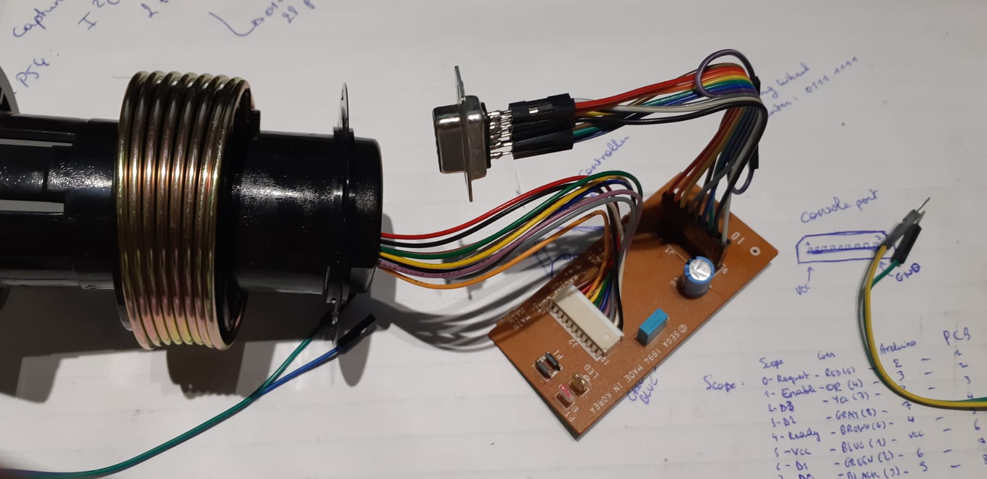
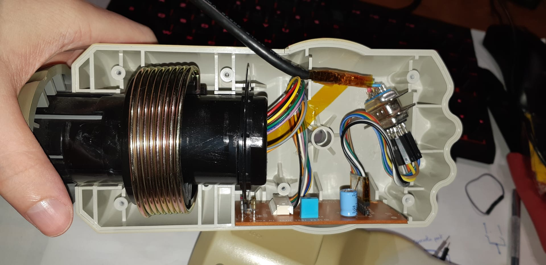
So first things first is take the controller apart.

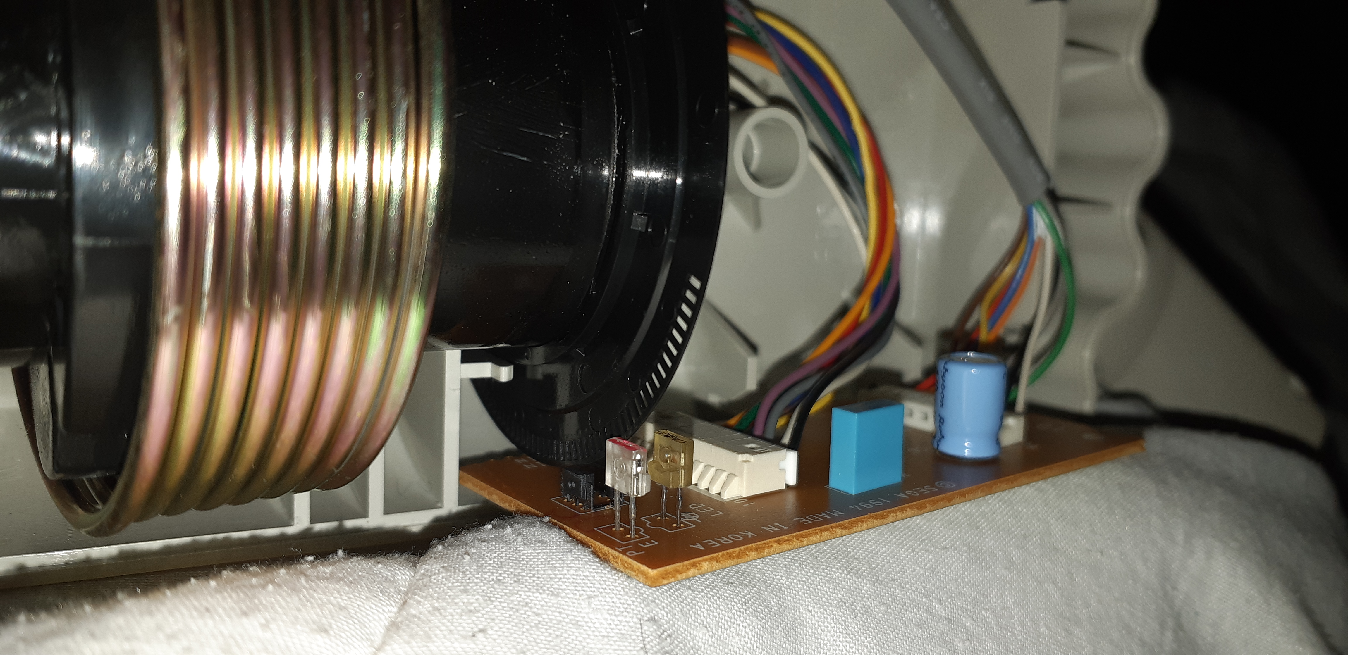
There’s a couple wires for the buttons going to the PCB.
The interesting thing is how they read the position of the steering wheel. It looks like an encoder.
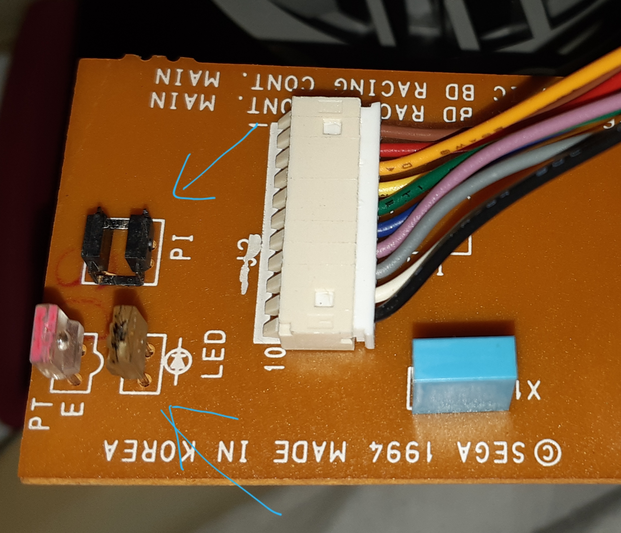
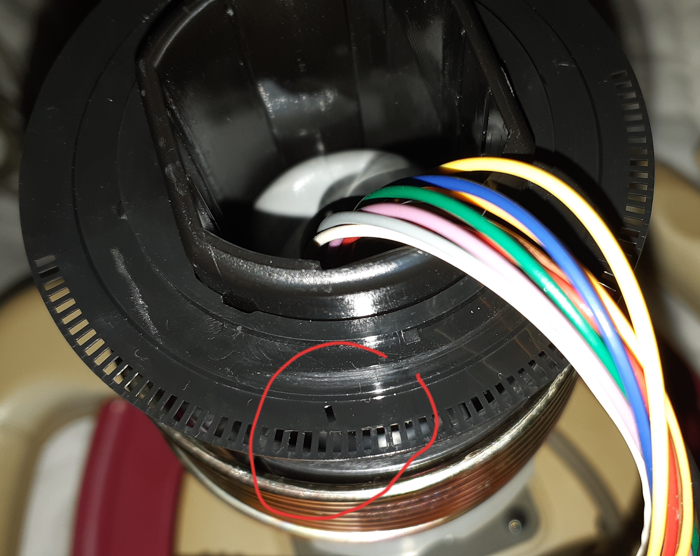
The board has a two IR receivers/transmitters that look through the little holes of the steering wheel.
These generate pulses for the controller chip which uses it to know the position of the steering wheel.
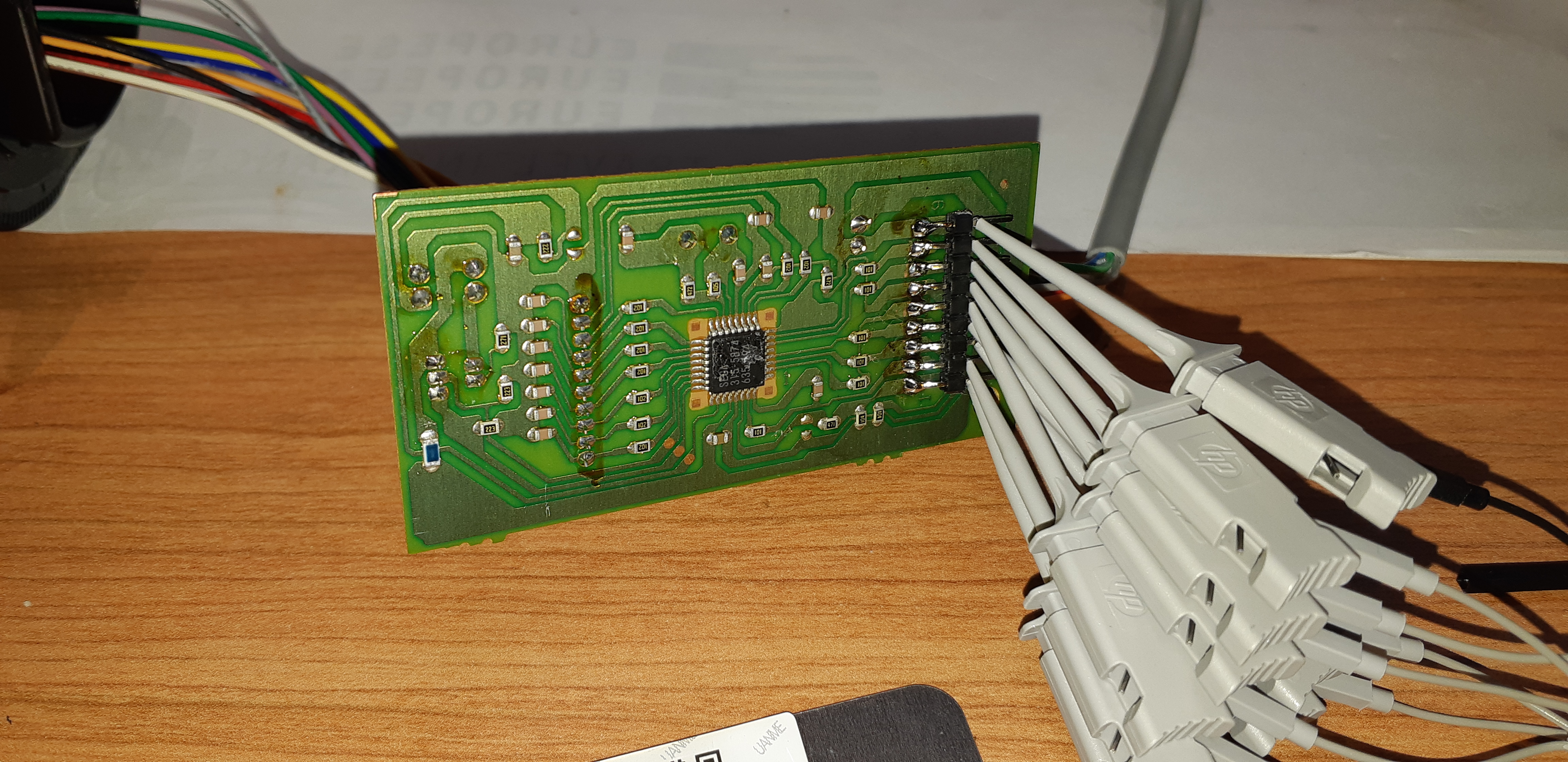
Here’s the proprietary Sega chip on the board. Of course no info on the internet.
Communication reverse engineering
Next thing to do was reverse engineer how the steering wheel actually works.
I added a few header pins on the cable going to the Saturn so I can probe the channels with my beautiful HP54645D.
After playing around with the steering wheel I rearranged the data on the scope to something more logical.
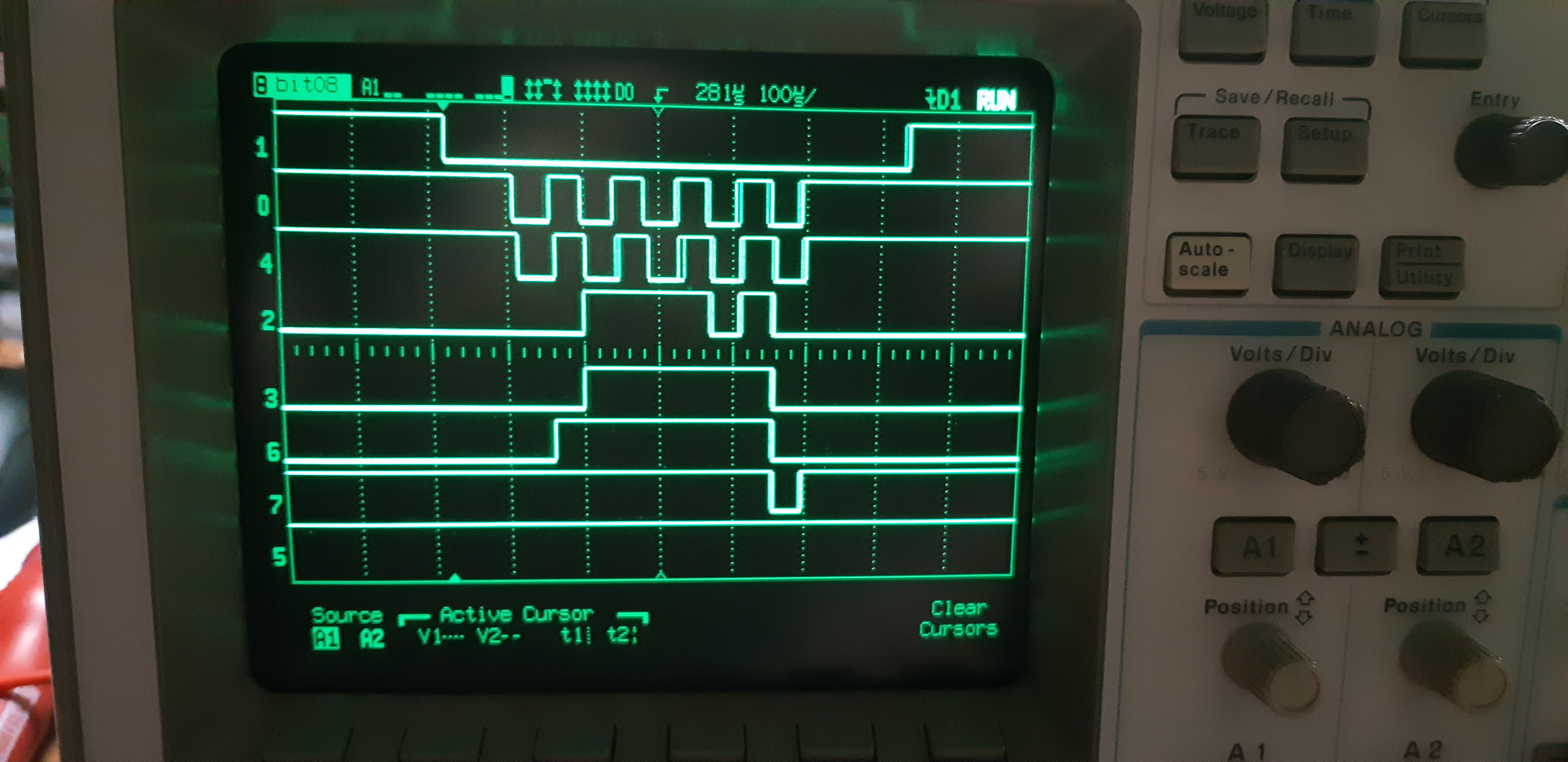
At first glance you can see some sort of chip select at the top, bit 1.
Then we have what looks like two clocks on bit 0 and bit 4.
Turns out the clock on bit 0 is actually a ‘request data’ from the Sega Saturn to the controller.
The clock on bit 4 is a ‘data ready’ signal from the controller to the Sega Saturn.
Bit 2, 3, 6 and 7 are data bits, which I’ve confirmed by turning the wheel and looking at the data changing. Also, when pressing buttons on the controller there are low pulses appearing on those signals.
Bit 5 is just vcc on the PCB.
Looking more into the location of pressed buttons in relation with the ‘request data’ and ‘data ready’ signal we can see that a data request happens on both falling and rising edge.
This means we have 10 packets of 4 bits sent from the controller to the Saturn.
The controller has a 9 buttons: UP, DOWN, A, B, C, X, Y, Z and START. The steering is also data sent to the Saturn.
Playing around with these buttons we can figure out their location in the packets:
- packet 0: unknown data (possibly controller ID ?)
- packet 1: unknown data (possibly controller ID ?)
- packet 2: DOWN - UP - unknown - unknown
- packet 3: B - C - A - START
- packet 4: Z - Y - X - unknown
- packet 5: unknown data
- packet 6: high nibble steering wheel position
- packet 7: low nibble steering wheel position
- packet 8: unknown data
- packet 9: unknown data
The steering wheel position is an unsigned byte so a value from 0 to 255.
The center position resets the byte to 127, which is also what you see on the scope.
Connecting to the PC
To connect to the PC I used an arduino pro micro which you can find tons of examples on making a USB device with.
It also has enough I/O for connecting to the steering wheel.
I want to be able to use the steering wheel on the PC and on the Saturn.
To do that I want to have two cables I can change with minimal effort.
One cable would have the arduino pro micro on it, and the other is the original cable.
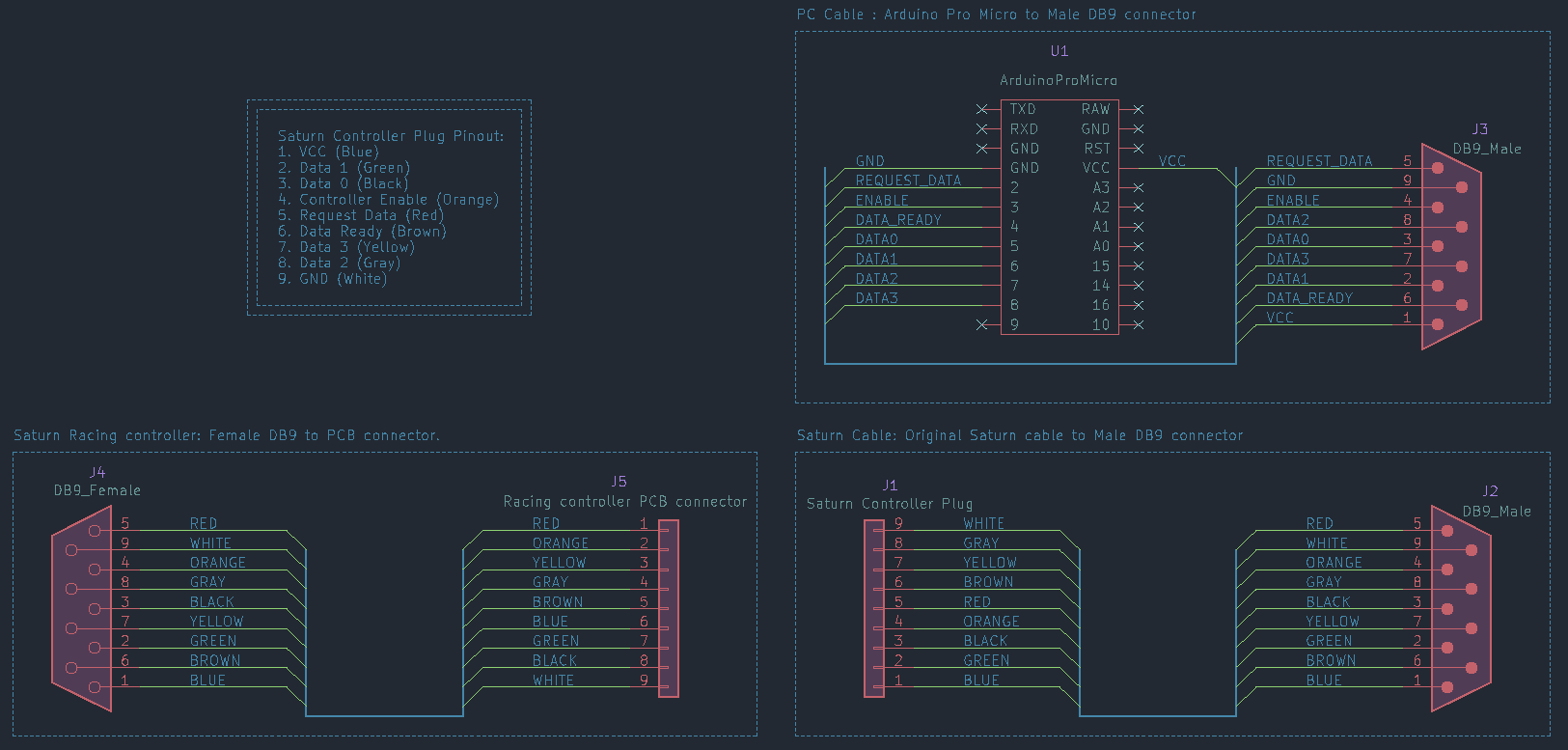
I wired a DB9 connector on the PCB.
The cable for the arduino pro micro and the original cable both got a DB9 connector too.
So now I can plug the arduino pro micro cable when I want to play on the PC and plug the original cable when I want to use it on the Saturn.
Here’s a schematic that shows how it’s all connected:
And here are a few pictures of the hardware:
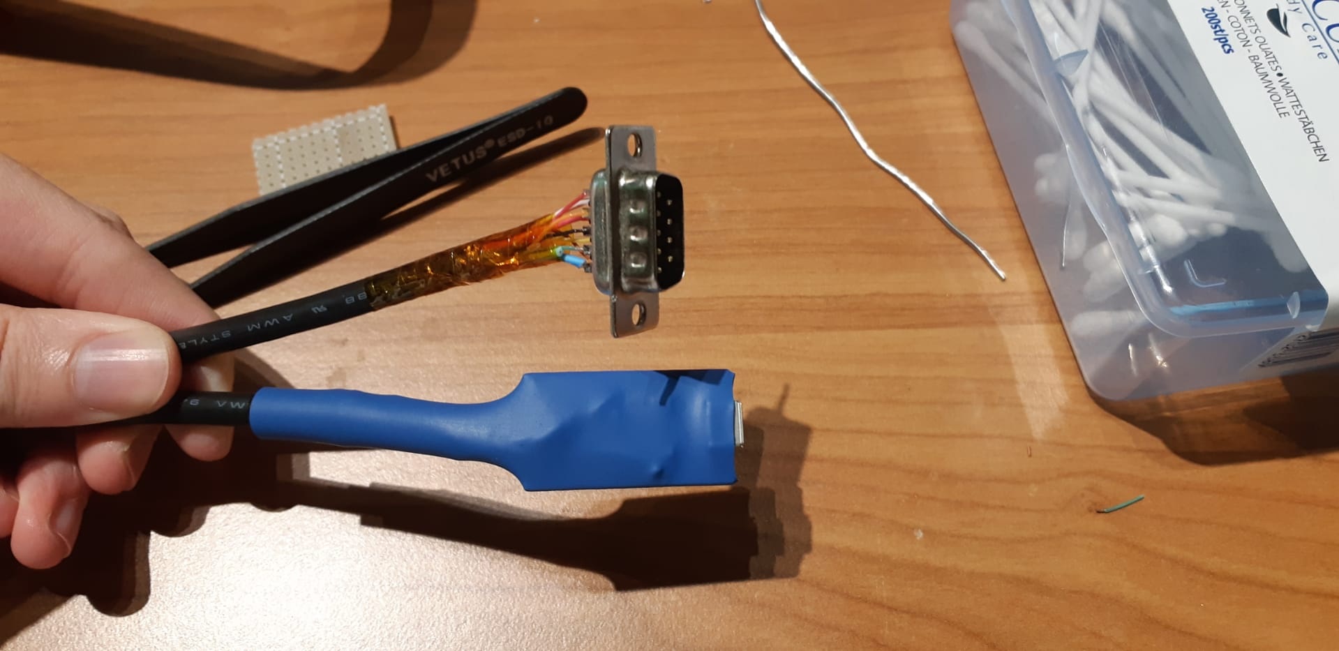
I used DB9 connectors because that’s what I had on hand, but I’d love to have a fancy round connector.
Maybe something like a DIN plug would work nicely here.
Arduino Pro Micro code
I’ve tried adding a few comments here and there to make it easier to understand.
The Saturn controller part uses a few helper functions and a special structure:
// Controller Structure
typedef struct{
    int16_t x;
    union{
        uint16_t buttons;
        struct{
            uint8_t btn_a: 1;
            uint8_t btn_b: 1;
            uint8_t btn_c: 1;
            uint8_t btn_x: 1;
            uint8_t btn_y: 1;
            uint8_t btn_z: 1;
            uint8_t btn_start: 1;
            uint8_t btn_up: 1;
            uint8_t btn_down: 1;
            uint8_t unused: 7;
        };
    };
}SaturnRacing;

// Initialize controller structure and I/O
void controllerInit(SaturnRacing *ctrl);
// Read controller data (ie. do the controller protocol magic here)
void controllerRead(SaturnRacing *ctrl);
// Used by controllerRead to make the controller protocol)
void controllerEnable(void);
void controllerDisable(void);
void controllerSendReadRequest(void);
void controllerRequestToIdle(void);
void controllerWaitForDataReady(void);
The structure contains an x-value which is the position of the steering wheel.
It also has a button word, which is then separated further into the individual button bits on the controller.
The controller functions are there to initialize the structure, reading the buttons and the steering wheel position.
The actual USB stuff uses the ArduinoJoystickLibrary which is super easy to use.
Just create a Joystick variable with whatever settings you want.
// Global joystick variable/object from Joystick library
Joystick_ j(
  JOYSTICK_DEFAULT_REPORT_ID, JOYSTICK_TYPE_JOYSTICK,
  9, 0,                  // Button Count, Hat Switch Count
  true, true, false,     // X on, Y on, Z off
  false, false, false,   // No Rx, Ry, or Rz
  false, false,          // No rudder or throttle
  false, false, false    // accelerator off, brake off, steering off
);
And initialize it in the setup() function of the arduino.
The main loop can be split into two parts:
- Reading controller data with
controllerRead(&controller) - Setting the USB data of the joystick structure.
void loop() {
  controllerRead(&controller); // Read controller status
  j.setXAxis(controller.x); // Set USB joystick X position
  j.setYAxis(127); // Set USB joystick Y position (probably not needed)
  // Set USB controller buttons
  j.setButton(0, controller.btn_a);
  j.setButton(1, controller.btn_b);
  j.setButton(2, controller.btn_c);
  j.setButton(3, controller.btn_x);
  j.setButton(4, controller.btn_y);
  j.setButton(5, controller.btn_z);
  j.setButton(6, controller.btn_up);
  j.setButton(7, controller.btn_down);
  j.setButton(8, controller.btn_start);
}
And that’s it.
All that’s left is plugging it into the PC and setting up the buttons in whatever game you want to use this into.