PlayStation 1 pedal controller
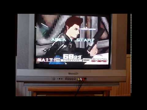
After working on the reset mod I got back into playing Time Crisis on the PlayStation.
I really wanted to play with a pedal button just like on the arcades.
I had read somewhere that you could put a 2nd controller in the PlayStation and step on it and it would work like a pedal button just like on the arcades.
Stepping on a controller was annoying though, so I made a custom pedal controller.
Here’s a demo of the pedal.
feikController
I dubbed the project feikController, as in fake controller -I know very clever-, because it’s obviously not an official controller.
The code is also more of a proof of concept for making a PlayStation 1 controller.
This fake controller just has one button, the pedal, and it’s set to the ‘X’ button.
It uses the same 16F18325 PIC microcontroller as the PlayStation reset mod.
The PCB is pretty much identical to it, except for a few layout changes and extra pads for the button input.


*Note that I haven’t actually tested the PCB. I’ve used a leftover reset mod PCB.
Communication
I’m pretty sure I already talked about the PlayStation communication in one of the previous posts, so I’ll let you look at those. I’m just going to recap how it works here.
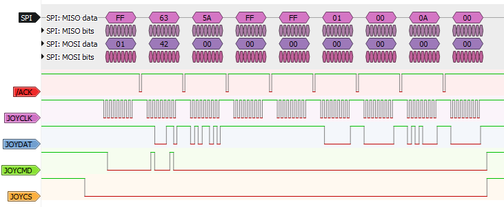
The PlayStation uses some sort of SPI interface to access the memory card and controllers with two chip select lines.
All devices are connected to the same SPI bus which contains: command (CMD), data, acknowledge (ACK) and two chip select lines.
Controller 1 and memory card 1 share the same chip select line and are further differentiated by an address sent by the PlayStation on the command line. Idem for controller 2 and memory card 2 but for the other chip select.
Every byte received from the PlayStation, ie. for every CMD, we also need to send an ACK pulse.
You can see a logic analyzer picture below showing a frame of communication with a guncon.
Code
I’m using the same structure from the reset mod.
This helps me read the commands, differentiate between the memory card and controller, and have a data buffer ready to send.
/* PlayStation Controller Command Union */
union PS1_Cmd{
    uint8_t buff[PS1_CTRL_BUFF_SIZE];
    struct{
        uint8_t device_select; // 0x01 or 0x81
        uint8_t command; // 0x42 for read switch
        uint8_t unused[PS1_CTRL_BUFF_SIZE-2]; // always 0 for controller
    };
};

/* PlayStation Controller Data Union */
union PS1_Ctrl_Data{
    uint8_t buff[PS1_CTRL_BUFF_SIZE + 1]; // buffer to read data
    struct{
        uint8_t unused1; // always 0xFF
        uint8_t id_lo; // id lo
        uint8_t id_hi; // id hi
        uint8_t keys_lo; // keys lo
        uint8_t keys_hi; // keys hi
        uint8_t unused2; // always 0xFF
    };
};
Sending data and receiving commands to and from the PlayStation happens with the SPI module of th 16F18325.
An interrupt is used to determine if the PlayStation is trying to read controller data or memory card data.
If it’s memory card data then our SPI module is disabled until the chip select is high, which indicates that the PlayStation finished reading data out of the memory card.
If it’s the controller then the content of the data buffer is sent byte by byte.
Because we still need to send an ACK and don’t want to pause in an interrupt, I set a flag high that will execute a piece of code in the main loop.
// Send Ack to PlayStation
if (send_ack){
    // Set the ACK pin to an output, LAT already to 0
    CLR_BIT(ACK_TRIS, ACK_OUTPUT);
    NOP(); // 125ns
    NOP(); // 125ns
    NOP(); // 125ns
    NOP(); // 125ns - 500ns
    NOP(); // 125ns
    NOP(); // 125ns
    NOP(); // 125ns
    NOP(); // 125ns - 1us
    NOP(); // 125ns
    NOP(); // 125ns
    NOP(); // 125ns
    NOP(); // 125ns - 1.5us
    NOP(); // 125ns
    NOP(); // 125ns
    NOP(); // 125ns
    NOP(); // 125ns - 2us
    NOP(); // 125ns
    NOP(); // 125ns
    NOP(); // 125ns
    NOP(); // 125ns - 2.5us
    SET_BIT(ACK_TRIS, ACK_OUTPUT); // Set ACK pin back to input
    send_ack = 0;
}
In this bit of code I’m setting a pin to an output LOW and waiting a bit with NOPs, then turning the pin back to an input as to not interfere with the other devices on the bus.
I’m using NOPs here because I need a very quick pulse of at least 2us.
Reading the button is just a matter of toggling the correct bit in the key status bytes.
// Read pedal switch status
if (GET_BIT(PEDAL_PORT, PEDAL_INPUT) != PEDAL_BUTTON_MODE){
    #if (PEDAL_BUTTON > 7)
        CLR_BIT(data.keys_hi, (PEDAL_BUTTON - 8));
    #else
        CLR_BIT(data.keys_lo, PEDAL_BUTTON);
    #endif
}else{
        data.keys_hi = CONTROLLER_BUTTON_RESET;
        data.keys_lo = CONTROLLER_BUTTON_RESET;
}
I’ve set the code up so that you can use either a normal open or normal closed button.
You just need to set the button up with the defines first.
You need 2 bytes to represent all the controller buttons.
Depending on which controller button you want to press through the pedal, you need to clear/set the correct bit in these bytes.
That’s why there is a check to see if PEDAL_BUTTON is higher than 7.
You can find the bit position for each button in the includes and here:
/* Controller Buttons */
#define BUTTON_SELECT 0
#define BUTTON_L3 1
#define BUTTON_R3 2
#define BUTTON_START 3
#define BUTTON_UP 4
#define BUTTON_RIGHT 5
#define BUTTON_DOWN 6
#define BUTTON_LEFT 7
#define BUTTON_L2 8
#define BUTTON_R2 9
#define BUTTON_L1 10
#define BUTTON_R1 11
#define BUTTON_TRIANGLE 12
#define BUTTON_CIRCLE 13
#define BUTTON_CROSS 14
#define BUTTON_SQUARE 15
The whole code is up on the feikController repo on github, go check it out for more info.
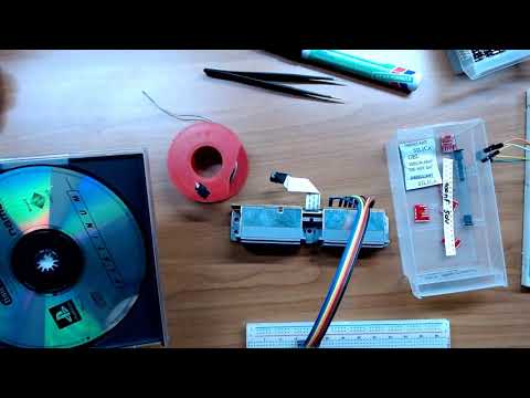
Making of
If you want to look at me struggling to make this then I have a playlist of the stream VODs up on youtube:
Other methods
For those that think this is a bit overkill for just emulating one button of a PlayStation controller, you are correct.
As mentioned before this is more of a proof of concept to make a controller, not specifically for just one button, but that’s the application I needed it for.
An easier way to make a custom controller is modifying an existing controller, but this was not the purpose of the project.
Future
I’m confident I can emulate whatever peripheral I want on the PlayStation 1 now.
With that said, I kind of want to make a TAS tool for the PlayStation but haven’t really put much thought into it.
I’m sure I’ll need to connect the TAS controller to a PC but don’t know yet what communication to use and what data will be transmitted.
I’ve put that idea on the todo-list. Who knows, maybe I’ll come up with something eventually.