Shooting bad guys, part 2
In part 1 I explained how the GUNCON works and what sensors are used in a Wiimote to do the motion sensing.
Part 2 will explain a bit more technical stuff about the GUNCON. We’ll see how to decode and make our own emulated GUNCON.
First, let’s check the resolution of the GUNCON.
Here in Europe, we use PAL encoding.
PAL has 625 scanlines with 576 active display lines (the rest is used for synching), 2 interlaced fields per frame and 25 frames per second refresh rate.
Because PAL is interlaced I’m not sure whether the Y coordinate is 576px or 288px (=576/2).
The X coordinate is a bit more difficult. Because the video signal for one line is an analog signal, you need some kind of counter to measure the length until a trigger is pressed.
I think that the 8MHz crystal is used for this purpose (see the reverse engineered schematic).
The analog signal of one video line is 64µs long. Of those 64µs, 1.65µs is used for the front porch, 4.7µs is used for the sync pulse and 5.7µs is used for the back porch. In the remaining 52µs there’s our displayed video signal.
From my understanding, the max X coordinate can now be calculated like this:
52µs * 8MHz = 416 px
This is something I’m not sure about, because problemkaputt.de mentions the GUNCON pixel width being 385.
I’ll get my hands on a CRT and will try to check what the lower and upper limits are.
After a quick google search I found someone near my home wanting to get rid of their CRT TV, so I took it home and spent the next 3 hours playing Time Crisis.
It’s been so long, you can’t blame me!
Decoding the data :
The RE schematic and pinouts found on problemkaputt.de suggest a data, command, clock, chip select and acknowledge line.
The PlayStation 3 memory card adapter wiki page on psdevwiki also mentions those lines.
They also mention that it’s similar to SPI, so let’s find out.
Again, problemkaputt already has the information about the different bytes sent by the GUNCON to the PlayStation.
Halfword 0 : Controller Info
	In our case this value is set to 0x5A63 for the Namco GUNCON
Halfword 1 : Buttons
	bit 3 : Button A (1 = released, 0 = pressed)
	bit 13 : Trigger (1 = released, 0 = pressed)
	bit 14 : Button B (1 = released, 0 = pressed)
	All other bits are set to 1
Halfword 2 : X position
	The 8MHz counter since HSYNC
Halfword 3 : Y position
	The scanlines since VSYNC
After setting up the Logic Analyzer and Sigrok with SPI decoder I got this:
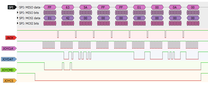
After measuring it with cursors, the clock has a period of 4µs, or 250kHz.
FYI: SPI is set up with LSb(it) first, CS polarity active-low = JOYCS, MISO = JOYDAT, MOSI = JOYCMD and CLK = JOYCLK.
Also, the LSB(yte) is sent first.
The capture above is when the GUNCON is pointed outside of the screen.
The GUNCON always sends who it is (0x5A63).
The X position is set to 0x0001 and Y position to 0x000A. This error code means you’re aiming outside of the screen.
Let’s find out what the max and min X:Y coordinates are.
The maximum Y coordinate I could measure is 0x124 or 292, the minimum is 0x26 or 38. Which gives us a height of 254px.
The minimum X coordinate is 0x54 or 84, the maximum is 0x1C6 or 454. Which gives us a width of 370px.
The origin of the GUNCON is the top-left side of the screen.
TODO : Measure break between SPI messages.
TODO : Check BA7071 sync IC output to GUNCON microcontroller.
Emulating a GUNCON :
Before we start our circuit with the Wiimote camera, I want to see if I can emulate the GUNCON using a microcontroller, analog joystick and 3 pushbuttons.
This will help in understanding the GUNCON further and might also reveal some unexpected behaviours which we will have to deal with in order to make our final circuit.
The analog joystick will be our X:Y coordinate and the 3 pushbuttons will be our A, B and trigger buttons.
Here’s a schematic I made for the GUNCON emulator:
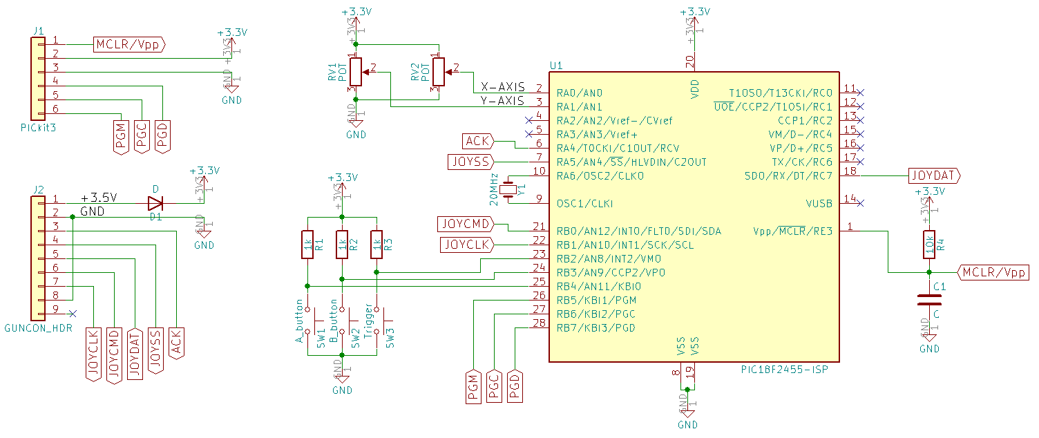
I’ll be using a Microchip PIC 18F2455, because that’s what I got on hand.
It’s been a little while but I think you can increase the external oscillator, which is 20MHz, with the internal PLL up to 48MHz.
That should give us plenty of time to work with.
Update: It turns out the PIC isn’t fast enough for how fast the SPI communication is going and generate the ACK signal at the same time. I’ll have to try something else.