Game Boy Oscilloscope, part 3
Recap:
In the October/November magazine of Elektor 2000, there was an article from Steve Willis who made a cartridge for the Game Boy named GBDSO.
This cartridge made the Game Boy into a 2 channel oscilloscope.
These are it’s key features :
- Dual trace display
- Sampling Rate: DC to 1 Msps
- Time Base: 100 s to 5 µs/Div
- Inputs: AC/DC 1 MegOhm
- Input gain: 50 mV to 10 V/Div
- Line or chart recorder trace modes
- Real-time FFT mode with dB scale
- Variable persistence XY mode
- PC link for screen or data transfer
- 5 hrs operation from NiMH batteries
- Averaging and Auto trigger functions
- Reference trace storage
As you can see from the features, this thing is pretty damn cool.
Who knew the Game Boy could do even half of it, let alone real-time FFT?
The GBDSO was a kit sold by Elektor, but because this project is old, they don’t seem to be selling it anymore.
I’m interested in having one of these, so I thought: Why don’t I make one?
Dead in the water
Having worked for a couple months on this project in 2019 and not getting the results I wanted I kind of left it to the side.
As you might remember from part 2, I had a couple different issues with footprints and PCB design.
I wasn’t sure the EPROM survived all the soldering to be honest.
Some stuff happened in 2019 which made me put this project on pause.
Back from the dead
In April and later in December 2020 I got to work on this again and fixed a few errors.
First thing I did was fix all the footprints to match the actual ICs I have.
This was fairly easy to do.
The symbol for the DS1267 digital potentiometer had pin 12 and pin 13 swapped.
This one came from the KiCad library which unfortunately contained the error and I didn’t double check it.
I opened an issue with KiCad, fixed the symbol myself and made a pull request to get this fixed.
Next, I compared the schematic from the GBDSO article with mine and found a couple errors in mine.
Here are a few of the errors I made on the schematic:
- BAV199 was connected to +5V instead of +5VA
- A14 and A15 were switched on the 74HC138 demultiplexer
- Voltage divider on TL072 wasn’t correct
- The bias voltage on the digital pot had a capacitor in series instead of parallel

Most errors are attributed to my inattentiveness while recreating the schematic and copy-pasting.
At this point I was confident about my schematic and board, so I ordered a new batch from JLCPCB.
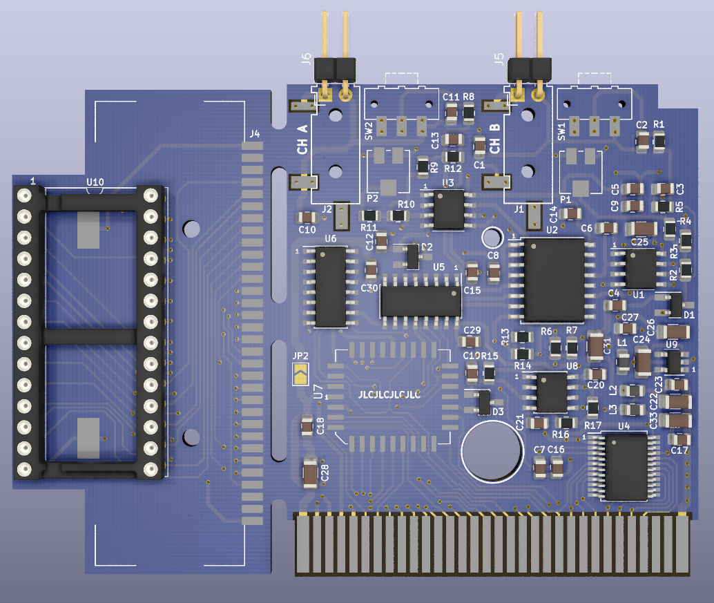
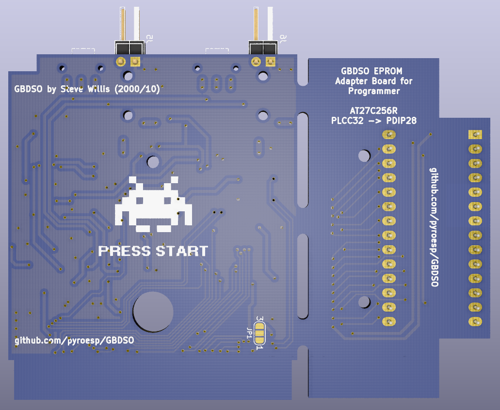
I really love the KiCad 3D view. Look how pretty the board is.
Third time’s a charm
When I got the board from JLCPCB it looked exactly like the 3D model.
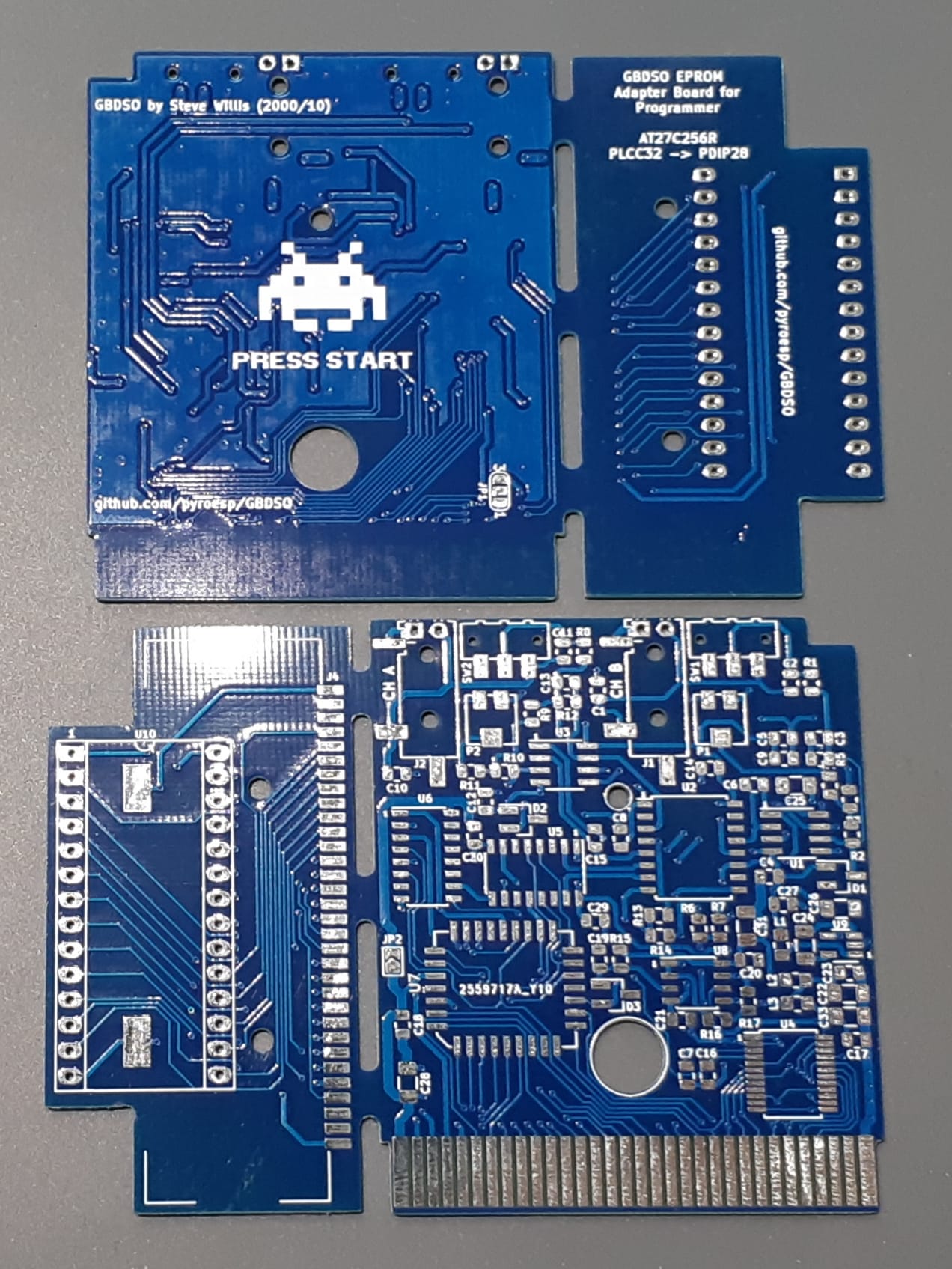
I did a visual inspection and everything looked nice.
Only thing left is to populate the board, so I got my red GBDSO and started salvaging all components from there and putting them on the blue board.
When I got to the AT27C256R I put it in my TL866II+ and read it’s content to see if it still worked and to have a backup just in case.
I also compared it to the bin file that’s floating around the internet named something like GBDSO v3.6, and that’s exactly the same as mine.
I managed to get all the components except for the DS1267 digital pot and the MAX114 ADC.
If you remember in part 2, I had to bend the pins inwards to get it soldered on the incorrect footprint.
I haven’t tried, but if I were to bend the pins back I’m sure they would just break.
.jpg)
Anyways, once everything was soldered I did a visual inspection and a short circuit inspection.

Everything looked like it was going to work, so I put it back in the cartridge and plugged it into my Game Boy.
I was greeted with the oh so familiar Nintendo ping sound and then the GBDSO menu.
After playing around a bit with it I didn’t see anything wrong with the channels like I did on my red board.
Here’s a picture of me measuring the same square wave on channel 1 and channel 2 on different timebases:


I’m so glad it’s finally working. I probably could have gotten it to work in 2019 if I had percevered a bit more, but oh well…
I’ve shared it amongst friends and different social media platforms and the reactions were always nice, which is good to see.
Elektor, release the bin file
When I first started this project I talked with a few people from Elektor to get them to release the EPROM file, which they were discussing.
I even went so far as contacting the original designer, Steve Willis, to see if he would be willing to release the files.
He agreed with me that open sourcing the project now would be a great idea, but as Elektor bought the design from him, he still felt olbigated to Elektor not to release any files without their consent.
What he also said was that if Elektor would be happy to release the files he’d be happy too.
Now that the project was pretty much all done, I tweeted Elektor to see if they were willing to release the bin file.
They’re not sure they still have the bin file but all I need is their consent and I can put my backup on the github repository.
As of the time of writing this post I haven’t had a positive reply, so let’s hope for the best!
That’s all for this project, for now at least.
I’ll update this whenever Elektor consents or not to releasing the bin file.